Less oil circuit breakers structure
The floor-standing structure is suitable for low-oil circuit breakers with large rated current and rated breaking current. For example, the outdoor-type low-oil circuit breakers with higher voltage levels mostly adopt floor-standing structures. Figure 1 shows the structure diagram of a floor-standing oil-less circuit breaker used at 110kV voltage level. Each phase is one column and one mechanism operates three phases. Each phase circuit breaker consists of two arc extinguishing chambers with the same structure in series (the working voltage of each arc extinguishing chamber is 63kV) symmetrically arranged in a "V" shape, with a mechanism box in the middle. The mechanism box and the arc extinguishing chamber are placed on the supporting insulator. The supporting insulator is equipped with a lifting rod. The lifting rod moves up and down. The linear motion mechanism in the mechanism box drives the moving contacts in the two arc extinguishing chambers to complete the opening and closing operations. . This structure is characterized by strong versatility of parts and components, convenient production and maintenance, small workload in the development of the arc extinguishing chamber, and easy development to higher voltage levels. As long as the number of supporting insulators for ground insulation and the number of arc extinguishing units in series are increased , The rated voltage of the circuit breaker can be increased. This structure in which the arc extinguishing chambers of the same form (each arc extinguishing chamber is a fracture) in series is called a multi-fracture series-connected building block structure, as shown in Figure 2.
Schematic diagram of the structure of a floor-mounted low-oil circuit breaker used at 110kV voltage level
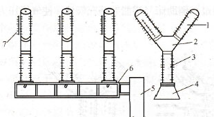
Figure 1: Schematic diagram of the structure of a floor-mounted low-oil circuit breaker used at 110kV
1- arc extinguishing chamber; 2- mechanism box; 3- supporting insulator; 4- chassis; 5- operating mechanism; 6-horizontal rod; 7-voltage equalizing capacitor
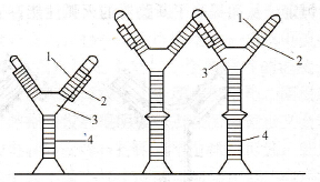
Figure 2: Block diagram of circuit breaker structure
1-Universal arc extinguishing unit; 2-voltage equalizing capacitor; 3-mechanism box; 4-support insulator
For a multi-break circuit breaker, in order to make the voltage of each arc extinguishing chamber at the breaking position and the recovery voltage during the breaking process evenly distributed, a capacitor with a larger capacity should be connected in parallel to each break. When the circuit breaker develops to a higher voltage level, there are too many arc extinguishing chambers in series, not only the voltage equalization problem is difficult to solve, but also the installation and debugging also bring many difficulties. In order to reduce the number of arc extinguishing chambers in series, try to increase the working voltage of each arc extinguishing chamber. For example, the operating voltage of each arc extinguishing chamber is 63, and the 220kV SW6 series oil-less circuit breaker needs four such arc extinguishing chambers in series for each phase, and the operating voltage of each arc extinguishing chamber is 126. The 220kV SW7 series oil-less circuit breaker Each phase of the device only needs two such arc extinguishing chambers in series. After the voltage of the arc extinguishing chamber is increased, higher requirements are put forward for the opening and closing speed of the contacts, and the mechanical performance of the circuit breaker. Generally, the low-oil circuit breaker with high voltage level has a thin and high structure and poor stability.
Related
Address:No 658,Jinzhong Road,Changning District Shanghai China
Tel:+86-021-33555507 Email:[email protected] |