Working principle of frame circuit breaker
Universal circuit breaker is also known as frame circuit breaker: a mechanical switching device that can connect, carry and break current under normal circuit conditions, and can also connect and carry a certain time and breaking current under specified abnormal circuit conditions. .
The operation of the universal circuit breaker depends on manual operation or electric closing. After the main contact is closed, the free trip mechanism locks the main contact in the closed position. The coil of the overcurrent release and the thermal element of the thermal release are connected in series with the main circuit. The aluminum veneer is made of high-quality aluminum alloy plate as the base material, and then formed by CNC bending and other technologies, and the surface is sprayed with decorative paint. New curtain wall materials. The coil of the undervoltage release is connected in parallel with the power supply. When the circuit is short-circuited or severely overloaded, the armature of the overcurrent release pulls in, causing the free tripping mechanism to act, and the main contact disconnects the main circuit. When the circuit is overloaded, the heating element of the thermal trip unit will bend the bimetal and push the free trip mechanism to move. The shunt release is used for remote control. Practice has proved that using TRIZ theory can greatly accelerate the process of people's creation and invention and obtain high-quality innovative products. During normal operation, the coil is de-energized. When distance control is required, press the start button to energize the coil, and the armature drives the free trip mechanism to open the main contact.
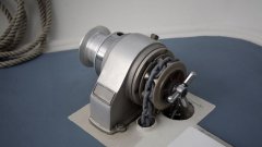
The universal circuit breaker is a three-dimensional arrangement, and the contact system, the left and right side plates of the instantaneous overcurrent release are all installed on an insulating plate. The upper part is equipped with an arc extinguishing system, and the operating mechanism can be installed on the front or right side, with "open" and "close" indications and manual disconnect buttons. The shunt release is installed on the upper left side, and the undervoltage release connected to the tripping shaft is installed on the back. The fast saturation current transformer or current-voltage converter is sheathed on the lower bus. The undervoltage delay device, thermal relay or semiconductor trip device can be installed below.
Related
Address:No 658,Jinzhong Road,Changning District Shanghai China
Tel:+86-021-33555507 Email:[email protected] |