Analysis on technical problems of frame circuit breaker
The analysis of the technical problems of the frame circuit breaker product presents the development history, structure and key technology, installation and accessories, common fault analysis and other contents of the frame circuit breaker for the customer in an all-round way.
01. Development history of frame circuit breaker
Definition of low voltage circuit breaker:
It is a mechanical switching device used in low-voltage power grid (AC50Hz / 60Hz), with AC rated voltage of ac1140v (DC1500V) and below, which can connect, carry and disconnect the current under normal circuit, and also can connect, carry and disconnect the current under specified abnormal current (such as short circuit) for a certain time.
Definition of frame circuit breaker:
It belongs to a type of low-voltage circuit breaker, also known as universal circuit breaker, which is used to distribute electric energy and protect overload, undervoltage and short-circuit protection of lines and power supply equipment. Generally, it has an insulating frame structure (fixed type) or a steel frame structure (drawer type), and all parts are installed in the frame.
It has a large capacity (rated current of 200A ~ 8000A), can be installed with multi-functional release and various accessories, and has high breaking capacity, dynamic and thermal stability. Therefore, it is often used in places requiring high breaking capacity and selective protection.
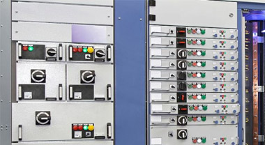
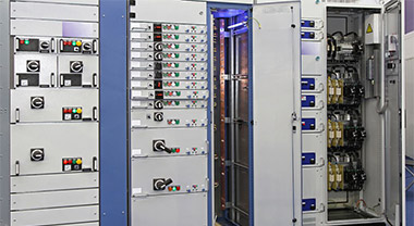
Application of frame circuit breaker in power system:
Application system: the frame circuit breaker is close to the transformer side, and the current of the frame circuit breaker is relatively large (800 ~ 6300A).
Product advantages: it can measure more than 150 parameters, assist in analyzing power quality, harmonic analysis, etc; Chinese and English display, display power supply, support three protocols; Multiple locking devices to improve safety.
Development history of circuit breaker:
The first generation of products: in the 1960s, it was designed and developed by completely imitating the products of the former Soviet Union. It only has short-circuit (instantaneous) protection, large structure size, large material consumption (copper), low performance index and incomplete varieties and specifications.
Second generation products: imported foreign advanced technology in the 1970s and 1980s. With overload long delay, short-circuit delay and instantaneous protection, the technical indicators are significantly improved, the volume is reduced, the structure is suitable for the requirements of the complete set of equipment, and the material consumption is still high.
Third generation products: in the mid-1990s, with the improvement of virtual prototype technology, test equipment and technology, arc theory research, and key materials research of low-voltage electrical appliances, new products and technologies constantly emerged.
Fourth generation products: since this century, the design has been optimized on the basis of the third generation products. It is characterized by miniaturization, increased working voltage to ac1140v, ICU = ICs = ICW, higher mechanical and electrical life, multiple wiring modes, multiple accessory functions, more perfect and humanized intelligent (Communication) level, and increased DC products.
02. Structure and key technology of frame circuit breaker
Explanation of common technical terms of frame circuit breaker:
- 1. Installation mode: fixed type, drawer type;
- 2. Protection grade: foreign matter prevention, waterproof grade and IP protection grade of electrical appliances;
- 3. Pollution level: the impact of micro environment on the use of circuit breaker is divided into 1-4 levels;
- 4. Electromagnetic interference: A or B, related to electromagnetic compatibility. ACB is generally class a [strong magnetic interference];
- 5. Use category: A or B, the difference is that class B has selective protection, i.e. short endurance requirements;
- 6. Installation category: impact resistance category (overvoltage category), 3-control circuit, 4-main circuit;
- 7. Number of poles: 3P, 4P;
- 8. Service life: mechanical service life (including maintainable and non maintainable service life) and electrical service life;
- 9. Wiring mode of main circuit: horizontal, vertical, extended, mixed, L-shaped, front of board (frame, molded case circuit breaker);
- 10. Power frequency withstand voltage: effective value of power frequency sinusoidal voltage without breakdown;
- 11. Impulse withstand voltage: the highest peak value of impulse (transient) voltage with certain shape and polarity that does not cause breakdown;
- 12. Creepage distance: between two conductive parts measured along the insulation surface, under different conditions of use, 13. The insulation material around the conductor is electrified, resulting in the charged area of the insulation material. Related to the insulation performance of the circuit breaker;
- 14. Electrical clearance: the shortest linear distance between two conductive parts.
Explanation of common codes of frame circuit breaker:
1. Technical parameter code:
Rated shell frame current: INM; Rated current: in; Rated insulation voltage: UI; Rated working voltage: UE; Rated impulse withstand voltage: Uimp; Rated frequency: F
2. Protection type code:
Setting value of long delay overload protection current: IR (TR); Short circuit short delay protection current setting value: ISD (TSD); Setting value of short-circuit instantaneous protection current: II; Setting value of grounding protection current: Ig (TG)
3. Breaking index code:
Rated operating short-circuit breaking capacity ICs; Rated limit short-circuit breaking capacity ICU; Rated short-time withstand current ICW; Rated short circuit making capacity (ICM)
Main standards for frame circuit breaker:
Relevant standards for low voltage switchgear and control equipment: GB / T 14048.1-2012, GB / t14048.2-2008, GB / T 14048.5-2008
Relevant standards for special environmental conditions: GB / T 19608.3-2004, GB / t20645-2006, GB / T 20626.3-2006
Other relevant standards: GB / T 2423.4-2008, GB / t4207-2003, GB / T 14092.3-2009
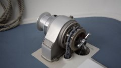
Introduction to main components of frame circuit breaker:
- 1. Contact system: including movable and static contact system, base plate and base plate (insulating thermosetting material), which are used to connect and disconnect current;
- 2. Arc extinguishing chamber: used to extinguish the arc;
- 3. Operating mechanism: it can manually store energy and conduct the closing and opening operation of the circuit breaker. In case of overload, short circuit and other faults, the circuit breaker can be automatically opened by the tripping action of the controller and its mechanism;
- 4. Electric operating mechanism: after the operating mechanism releases energy, it can automatically pre store energy instead of manual energy storage;
- 5. Controllers: they are all electronic and used for real-time protection, measurement and monitoring of grid operation. When the power network is in communication networking, the controller can realize remote measurement, remote signaling, remote control and remote regulation at the remote terminal of the power automation network. The controller is divided into LCD screen type, digital screen type and no screen dial code type according to the display category;
- 6. Drawer base: one of the core components of drawer type products. The circuit breaker body is installed in the drawer base. The drawer base connects the main circuit and the control circuit to facilitate the user to maintain the circuit breaker;
- 7. Shunt release: remote control circuit breaker opening;
- 8. Closing electromagnet: remote control circuit breaker closing;
- 9. Auxiliary contact: provide users with multiple sets of normally open or normally closed contacts to follow the closing and opening switching state of the circuit breaker;
- 10. Secondary wiring terminal: control circuit, accessory electrical state output, auxiliary contact state output, etc. are all connected through secondary wiring terminal.
Working principle of frame circuit breaker:
Working steps: before closing the circuit breaker, the operating mechanism shall be operated by the motor or manually to store energy. Press the closing button to close the dynamic and static contacts. Press the opening button to open the circuit breaker.
Fault handling steps: in case of overload or short-circuit fault, the controller judges the magnitude of overload or short-circuit current through the transformer, and sends a pulse signal to the executive unit. The executive unit acts to disconnect the operating mechanism and the contact system. When a short-circuit fault occurs, the moving and stationary contacts are disconnected, and a large number of arcs are generated between the contacts. The arcs are elongated with the opening of the moving contacts. After the arc is generated, the iron grid in the arc extinguishing chamber is magnetized to generate magnetic attraction, which leads the arc to the arc extinguishing chamber. The arc is divided into short arcs by the grid. The cooling effect of the grid on the arc is used to improve the arc resistance and arc voltage and extinguish the arc.
Closing and opening action of frame circuit breaker:
There are two modes of operation: electric and manual
Principle: external energy is provided to compress the spring, and through the cooperation of various levers of the operating mechanism, the movable contact moves to realize opening and closing
Key technologies of frame circuit breaker:
- Rated limit short-circuit breaking capacity Icu: O—T—CO
- Rated operating short-circuit breaking capacity Ics: O—T—CO—T—CO
- Rated short-time withstand current: short-time withstand + O—T—CO
Three positions of drawer type circuit breaker:
Connection position: both the main circuit and the secondary circuit are connected
Test position: the main circuit is disconnected, the secondary circuit is connected, and the necessary action test can be carried out
Separation position: the main circuit and the secondary circuit are disconnected, and the circuit breaker body can be taken out at this position
New requirements of industrial Internet for low-voltage circuit breakers:
More comprehensive parameter measurement and sensing capability: it is required to accurately and efficiently transmit the healthy parameters and operating system parameters of the circuit breaker;
It has strong interconnection capability, real-time system operation status and parameter monitoring, early warning and protection;
High reliability control and protection capability: grid protection, adaptive protection, load rejection, synchronous detection and grid connection
Application scenarios and characteristics of frame circuit breaker:
- 1. Application characteristics: closing and opening operations are not frequent; Automatic disconnection protection against overload, short circuit or undervoltage; With isolation function, it can be used as an isolation switch; It has multiple wiring modes; A variety of safety protection accessories are provided or added.
- 2. Application scenarios: power plants, civil buildings, data centers, wind power generation, photovoltaic power generation, etc
- 3. Typical application - New Energy: converter of wind power doubly fed system, wind power direct drive converter, wind power phase change system, etc
- 4. Typical application - Data Center: Data Center low-voltage power distribution, UPS battery pack, etc
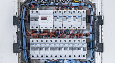
03. Installation and accessories of frame circuit breaker
Wiring mode of frame circuit breaker:
Horizontal wiring, vertical wiring, mixed wiring, horizontal extension wiring, vertical extension wiring, mixed extension wiring
Accessories of frame circuit breaker:
Controller, power module (st-iv), secondary wiring terminal, auxiliary switch, interphase separator, undervoltage release, closing / shunt coil, electric operating mechanism, mechanical interlock, door frame, counter, open position lock, relay module
Mechanical interlocking function:
- 1. Lever type mechanical interlocking: it can be used for vertical interlocking of 2 or 3 circuit breakers. The vertical distance of circuit breakers can be adjusted within the range of < 1m. One is closed and the other is open.
- 2. Wire rope type mechanical interlocking: applicable to drawer type circuit breakers, which can be used for vertical or horizontal interlocking of two circuit breakers. The maximum distance between interlocked circuit breakers is 2000mm, one is closed and the other is open
- 3. Installation: it shall be installed by the user according to the instructions, and the interlocking mechanism shall be installed on the right side plate of the circuit breaker
- 4. Commissioning requirements: control the coordinated action between the main shaft and the tripping shaft. When one is in the closing state, the other cannot be closed
04. Common fault analysis
The circuit breaker cannot store energy: the energy storage has been completed, or the manual energy storage is half, the storage capacity is required to be increased, or the control power supply voltage of the electric energy storage device is less than 85% us;
The rocker cannot be inserted into the circuit breaker: the drawer guide rail or the circuit breaker / disconnector body is not fully pushed in, or the padlock handle of the drawer seat is pulled out and locked;
The circuit breaker cannot be disconnected: due to mechanical operating mechanism failure, or the shunt release is damaged, or the control power supply voltage of the shunt release is less than 70% us;
There is no display on the circuit breaker control screen: the circuit breaker controller is not connected to the power supply;
Related
Address:No 658,Jinzhong Road,Changning District Shanghai China
Tel:+86-021-33555507 Email:[email protected] |