Analysis on technical problems of molded case circuit breaker
The analysis of technical problems of molded case circuit breaker products presents the development history, working principle, key technologies and other contents of the circuit breaker for customers in an all-round way.
01. Introduction and development history of circuit breaker
Definition of circuit breaker:
A mechanical switching device that can connect, carry and break the current under the normal circuit, and can also connect, carry and break the current for a certain time under the specified abnormal current (such as short circuit). Defined by GB / t14048.2 (iec60947-1).
Function of circuit breaker:
- 1. Isolation function and control function (functional, emergency on-off and disconnection for mechanical maintenance);
- 2. Protection function (overload, short circuit, insulation fault and undervoltage);
- 3. Remote control;
- 4. Indication and measurement;
- 5. With the development of more than ten years, the circuit breaker is developing towards intelligence.
Standard of low voltage circuit breaker:
Among the current standards, IEC (International Electrotechnical organization) is the most widely used in the world, and more UL standards and Japanese JIS standards are used in North America. The domestic standard GB / t14048.1 ~ 2 is basically consistent with iec60947-1 ~ 2. With the continuous development of domestic low-voltage electrical equipment technology, it has gradually exceeded the requirements of IEC standards in some fields.
System introduction:
- 1. The frame circuit breaker is near the transformer side, and the current of the frame circuit breaker is relatively large (800 ~ 6300A);
- 2. Molded case circuit breakers (10-1600a) are widely used in branch boxes, including thermal magnetic, electronic and leakage;
- 3. Small circuit breakers are usually used in the household;
- 4. The role of the circuit breaker in the whole system: static as if the circuit is smooth and continuous under the normal working current; dynamic as if the circuit is loose (it can be cut off quickly in case of fault current)
Development history of circuit breaker:
- 1. Joint development era: Molded Case switches of the Soviet Union: A3, A15. In 1957, Shanghai Institute of electrical science was established: dz10 DW10 RT0 was jointly developed by the Institute.
- 2. Learn from the era of foreign advanced products: Exchange Technology for market, promote the rapid improvement of the domestic market through the introduction of foreign advanced technology, and bring problems of different sizes.
- 3. Independent development era: with the improvement of virtual prototype technology, test equipment and technology, arc theory research, and Research on key materials of low-voltage electrical appliances, new products and technologies continue to emerge, for example, DC voltage can reach 1500V and AC voltage can reach 1000V.
02. Working principle of molded case circuit breaker
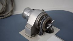
Molded case circuit breaker structure:
It consists of shell (base, cover), conductive system (moving contact, stationary contact and connecting row), handle operating mechanism (for opening and closing), controller protection unit (for setting protection parameters and display), plug-in communication interface (intelligent circuit breaker, for uploading circuit breaker data).
Concept of isolation:
Isolation is to ensure that there is obvious fracture in the whole circuit during maintenance to ensure the safety of maintenance. The fracture needs to bear a certain current and voltage. At the same time, the handle needs to indicate the status and position of the moving and stationary contacts to prevent the workers from still carrying out maintenance operations when the welding of the moving and stationary contacts occurs, resulting in casualties.
Core parameters of molded case circuit breaker:
- 1. Rated limit short-circuit breaking capacity ICU: o-t-co (breaking closing and breaking);
- 2. Rated operating short-circuit breaking capacity ICS: o-t-co-t-co (breaking closing and breaking closing in breaking), applicable to scenarios requiring multiple breaking capacities;
- 3. The breaking capacity of short circuit is related to the voltage, which should be paid attention to during the selection;
- 4. Breaking level: C, l, m, h, representing the breaking capacity of the circuit breaker under the same shell frame (higher and higher);
- 5. Pay attention to the difference between the shell frame current INM and the rated current in during model selection.
Protection of circuit breaker:
- 1. Electronic circuit breaker: generally, the current in the inductor induction circuit is used to determine the actual current through CPU calculation and compare it with the set protection current. If it exceeds the set value, the command will be issued and the actuator will be disconnected;
- 2. Thermal magnetic overload protection: heat is generated after current overload, and the heat is transferred to the bimetallic sheet, which causes the bimetallic sheet to bend, and the actuator will be triggered after bending to a certain extent.;
- 3. National standard: under normal conditions, the molded case circuit breaker cannot operate under 1.05 times of the set current, and it will break at the agreed time when the current is greater than 1.3 times;
- 4. Short circuit protection: when the short-circuit current flows through the coil, the electromagnetic force is generated to make the iron core move downward against the spring force, unlock the locking device and trigger the four-bar linkage to open the moving and stationary contacts;
- 5. IR: overload setting current, set between 0.8-1in;
- 6. Im: short circuit setting current, set between 5-10in.
03. Key technology of molded case circuit breaker
Short circuit breaking technology: see the protection of circuit breaker above for details
AC Short-Circuit Breaking and DC short-circuit breaking: the current in the AC system has zero crossing point, which is easy to break,
The DC system has no zero crossing point, the fault current is very large, and it is difficult to break. It needs specially designed breaking system, arc extinguishing system and contact system to realize protection. With the development of technology, the size of DC circuit breaker is miniaturized, the contact loss is small, the loss is reduced, and there is no need for internal short circuit.
Current limiting technology
Reduce the harm of short-circuit current to lines, equipment and circuit breakers.
This hazard is reflected in three aspects:
- 1. Thermal effect: damage to insulation and accelerate aging of insulation materials;
- 2. Electrodynamic effect: deform and damage the equipment or its parts;
- 3. Electromagnetic effect: the electromagnetic field generated by the sudden change of current has an impact on the surrounding electromagnetic interference, especially on the electronic equipment.
Selectivity of cooperation between upper and lower levels
- 1. In case of fault (overload, short circuit and insulation), it can only be tripped by the superior circuit breaker closest to the fault point. Ensure the continuity of power supply to the fault free circuit.
- 2. Current selectivity: the current of the upper and lower circuits is different. The current of the upper circuit breaker is 2-2.5 times of the current of the lower circuit breaker. It can basically ensure that no skip tripping occurs;
- 4. Time selectivity: mainly used for setting on electronic circuit breakers, such as short-circuit short delay;
- 5. Logic selectivity: mainly by setting logic programs of upper and lower circuit breakers;
- 6. Energy selectivity: it is generally selected by the energy selectivity table provided by the manufacturer.
04. Intelligent circuit breaker
Intelligent power distribution system: the operation data is collected by the bottom intelligent equipment and transmitted to the local server or cloud through the network information to make the power distribution system digital and intelligent;
Features of intelligent circuit breaker: high-precision measurement of current and voltage, component status, one key query, remote operation, unmanned test, fault warning, prevention, real-time alarm, accurate positioning, health prediction, and accident avoidance;
Health prediction of intelligent circuit breaker: operation times, life health, contact wear and temperature health.
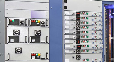
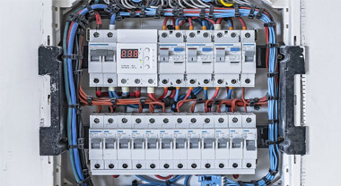
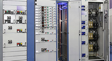
05. Circuit breaker installation and accessories
Installation mode of circuit breaker:
Front board wiring (the most widely used), rear board wiring, plug-in front board wiring, plug-in rear board wiring, manual operating mechanism and electric operating mechanism.
enclosure:
- 1. Internal accessories: undervoltage release, shunt release, alarm contact, auxiliary contact, auxiliary alarm contact, etc; External accessories: wiring post behind the board, plug-in wiring floor behind the board, draw out floor, manual and electric operating mechanism, etc;
- 2. Alarm contact: alarm contact is one of auxiliary contacts. This auxiliary contact does not act when the circuit breaker is normally closed and opened. Only after free tripping (or fault tripping) can the contact change its original state, that is, the normally open switch is closed and the normally closed switch is open. After the circuit breaker is closed again, the contact will return to its original position;
- 3. Undervoltage release: if the working voltage exceeds the rated value, it is called overvoltage; if the working voltage is lower than the rated value, it is called undervoltage. In the standard, 35% ~ 75% is under voltage (the circuit breaker must act), 10% ~ 35% is under voltage (the circuit breaker must not be closed), and more than 110% is over voltage (the circuit breaker must act);
- 4. Shunt release: it is an accessory for remote control product opening. That is, the given voltage signal triggers the shunt coil to be energized and then drives the product to trip.
06. Common fault analysis
- 1. Handle fracture: it is caused by operation exceeding the stroke or falling without protection;
- 2. Terminal damage: the screw is not tightened, resulting in high temperature rise and burning, or the sliding wire cannot be tightened due to excessive torque;
- 3. Poor characteristics: thermal magnetic type early jump due to high ring temperature, or electronic gear selection error;
- 4. Internal and external accessories: the function is abnormal due to improper assembly of accessories, or the accessories are damaged due to abnormal operation.
Related
Address:No 658,Jinzhong Road,Changning District Shanghai China
Tel:+86-021-33555507 Email:[email protected] |