Circuit breaker control circuit principle diagram
Refers to a device for producing a direct electrical equipment, transport, distribution of electric energy, including a generator, power transformers, circuit breakers, disconnectors, bus, cable, and power transmission lines, etc., constitute the main power system. The secondary device is a condition for a power system and equipment for monitoring, control, regulation and protection of low voltage electrical equipment, including measuring instruments, communications equipment. Between the secondary equipment interconnected loops collectively referred to as the secondary circuit, which is to ensure the safe production of power systems, economic performance and reliable power supply indispensable important component.
This article briefly describes the basic principles of circuit breaker control loop, starting from the most basic circuits, gradually adding anti-tripping circuit and latch circuits, and circuit to do some improvement. Of course, the circuit diagram given herein are only the most basic to explain its basic principles, the practical application of the circuit is much more complex.
1. The most basic circuit diagram:
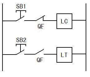
SB1: Closing switch SB2: OPEN switch QF: a circuit breaker auxiliary contact LC: closing coil LT: opening coil which principle of operation is very simple, not then repeat.
2 Increased down circuit:
the presence of a loop above problem: if SB1 pressed, at a time when failure protection devices immediately present operation circuit, trip the circuit breaker, this process occurs almost instantaneously, while the operator is still time to release SB1, then QF SB1 circuit breaker tripped due undone closed again, this time will lead to LC energized again, closing the circuit breaker again. And so forth, there have been "jump."
If the closing is successful, but for some reason SB1 adhesions can not be turned off, then when the operator pushes SB2 to perform an opening, due SB1 adhesions, it will also lead to a jump phenomenon.
Jumping phenomenon of safety equipment and operating personnel constitute great harm, it is necessary to increase the anti-tripping circuit.
Increase of anti-tripping circuit diagram is as follows:
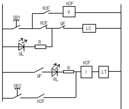
KCF (I): anti-skip current relay, the operation current reaches the limit, this circuit, in the failure to prevent the jump when closing
KCF ( V): anti-jump voltage relay, the voltage reaches the operation limit value, this circuit, when a jump operation to prevent opening faults in the process is as follows:
-
CLOSING:
- SBl press à green (GL) loss of power off,
- the LC energized à changing the state of the circuit breaker closing àQF à red (RL) light,
- KCF (I) [energized due RLAnd R is limiting, the coil opening operation is insufficient LT] àKCF each auxiliary contacts change state àKCF (V) to achieve the above energized state, the closing operation is completed, the process is almost instantaneous, SBl still time to release.
- In this case, if due to a failure, the protection device to trip the circuit breaker, since the holding action KCF (V) is, SBl diversion loop through the auxiliary contact KCF KCF (V) circuit of the LC no longer energized, thus avoiding the breaking again closing device, thus avoiding the occurrence of a jump.
- If the circuit is not faulty, the closing success. Then release SB1, the KCF (V) loss of power, but because of KCF (the I) remains energized, the KCF each auxiliary contact holder.
-
OPEN:
- SB2 Press àRL loss of power off,
- LT energized and reaches the current limit operation when opening àQF restored to an initial state in FIG à à breaker normal state, after a successful closing, each auxiliary contacts remain engaged KCF a state after the shutter, so that the branch SB1 via KCF (V) conduction à release SB2àKCF (I), KCF (V) are each energized à KCF auxiliary contact in the initial state in FIG recovery, GL circuit is turned on, green light [because the flow restrictor GL and R, the operation of the LC closing coil] If insufficient due to a failure, as the most typical adhesion SB1: Since each KCF successful closing of the auxiliary contacts remains after, this time, SB1 KCF diversion circuit (V ) circuit, the LC will not be energized again cause the circuit breaker closing, thus avoiding the occurrence of the bounding phenomenon.
3. The increase locked loop
Increases the control circuit proof Circuit has been some improvement, but there are still problems: Operating system problems such as circuit breakers (hydraulic pressure is too high or too low, such as spring energy has not been completed ), dividing this case, the closing operation, it is easy to lead points, closing the action fails. For example: the circuit breaker operating mechanism is a spring, spring energy if not completed, the points, the closing operation can not be completed, or not completed position, likely to cause damage to the device.
Therefore, the need to increase lockout circuit to prevent this from happening. Below the circuit breaker operating mechanism springs example, briefly explain increased spring accumulator latch circuit the secondary circuit.
Diagram is as follows:
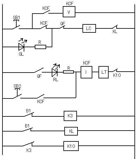
B1: when the closing spring charging is not completed
when the spring energy is not completed, B1 is closed, the coil K3, KL energized, eventually leading to the auxiliary contact KL, K10 jump in this case either closing or opening were unable to achieve the desired played a lockouteffect.
4. To further improve
Until the third quarter, the paper outlined the desired secondary circuit breaker has begun to take shape, but still need further improvement: lights RL and GL directly connected to the points where the closing coil circuit , if the power used is larger incandescent lamps, it will be in minutes, a greater pressure drop over the closing coil, and cut off points, a large voltage disturbance may be generated when closing coil incandescent lamp burn easily. To avoid the above disadvantages and to be connected to the intermediate relay points, closing the loop, then the relay contact is controlled by the indicator .
diagram is as follows:
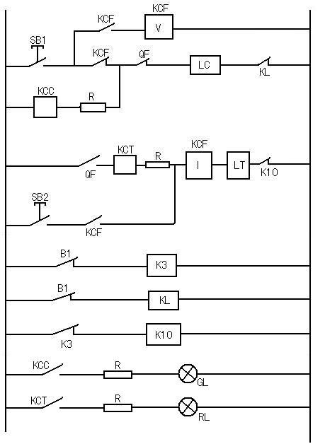
(the principle is relatively simple, not be repeated here)
Related

Address:No 658,Jinzhong Road,Changning District Shanghai China
Tel:+86-021-33555507 Email:[email protected] |