Internal structure diagram of miniature circuit breaker
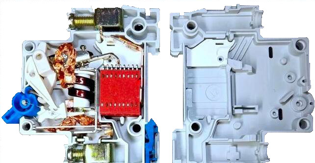
1. Internal structure
If the 4 rivets are damaged, you can split them in half, as shown in the figure below. The parts are embedded in the left cover, and the right cover can be removed.
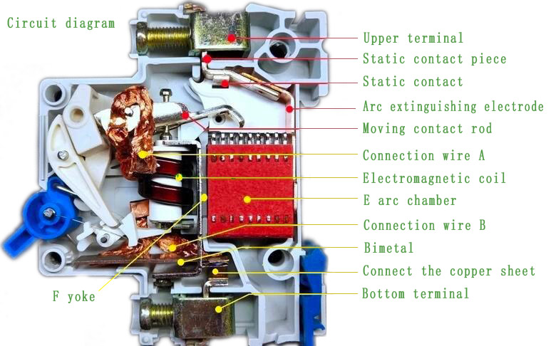
2. Circuit part
When the contact is closed, the circuit path is (set the direction from top to bottom): 1-2-3-5-6-7-8-9-11. When the contacts are disconnected, an arc current is generated between the contacts. The current path at the beginning is: 1-2-3-arc-5-6-7-8-9-11. After the arc is introduced into the arc extinguishing chamber E due to magnetism, heat, etc., the current path is: 1-2-4-E-F-10-11. The arc is divided into 10 segments in the arc extinguishing chamber, which are quickly cooled and extinguished. After the arc is extinguished, the current is completely interrupted.
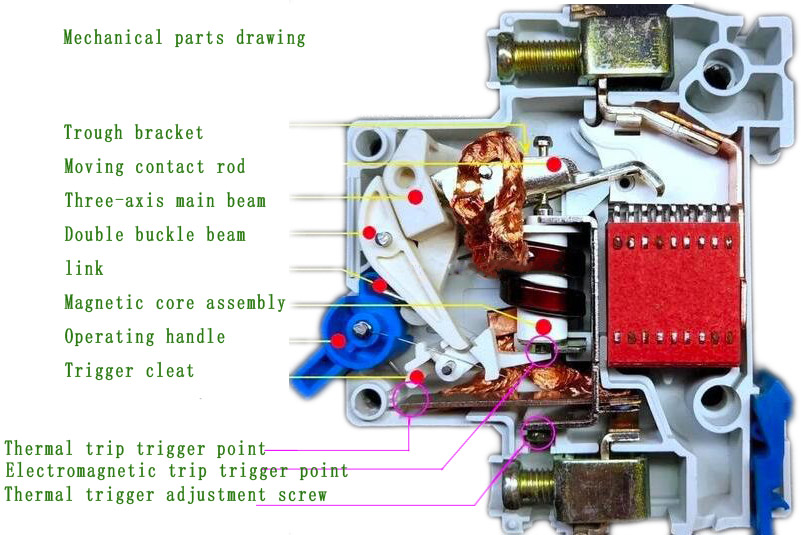
3. Mechanical part
The function of the mechanical part: support two operations of manual "on" and "off", and automatically perform "thermal trip" and "electromagnetic trip" for protection in case of overcurrent or short circuit. It also has "thermal trip current fine-tuning" operation (this function is not commonly used).
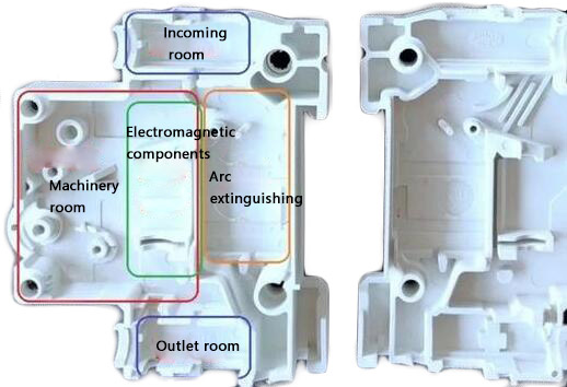
4. Shell
The housing size is in line with industry standards. In order to unify standards and improve processing efficiency, circuit breakers less than a certain rated current will use the same shell, contacts and terminals. The maximum rated current that this enclosure can pass is the "frame-level current". In this example, 63 in the model DZ47LED 63 means that the current of the shell frame of this series is 63A.
After the shell is disassembled into the left and right halves, it can be seen that most of the two halves are symmetrical. According to the function, the internal space can be roughly divided into "four-bedroom".
Related

Address:No 658,Jinzhong Road,Changning District Shanghai China
Tel:+86-021-33555507 Email:[email protected] |