Key Points of Molded Case Circuit Breaker Selection
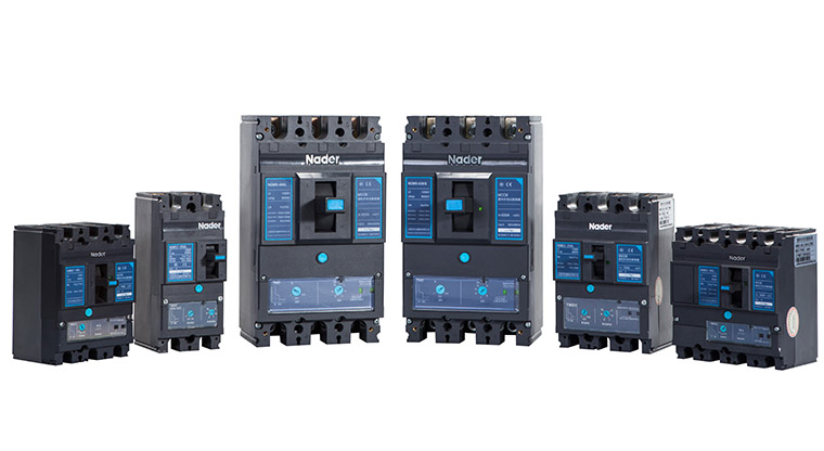
Circuit breakers are classified into universal type and plastic case type according to their structure. Among them, molded case circuit breakers are suitable for power distribution systems with rated voltage 690V, frequency 50/60Hz, and rated current 16 to 1600A or as protection equipment for transformers, motors, capacitors, etc. . It is mainly used for the distribution of electric energy, as overload, short circuit, leakage and undervoltage protection of various branches and electrical equipment, and can also be used for infrequent conversion of lines and electrical equipment. It is widely used in industry and agriculture, transportation, mining, civil construction, national defense and other sectors. It plays a great role in the transmission and distribution of electric power, and the control and protection of electric circuits. It is a product with a large amount of use and a wide range of products. Because users do not have a deep or comprehensive understanding of the characteristics and technical requirements of molded case circuit breakers, some concepts are easily confused with each other, and some deviations and misunderstandings often occur in practical applications. This article gives a detailed introduction to the important parameters that users need to pay attention to when selecting and using molded case circuit breakers to help users choose to use molded case circuit breakers.
1. Five important parameters that need to be paid attention to when selecting a molded case circuit breaker
1.1 Circuit breaker shell frame grade
The rated current of the circuit breaker shell frame refers to the rated current of the largest trip unit that can be installed in the frame and plastic case of the same basic size.
The rated current of the circuit breaker refers to the current that the trip unit of the circuit breaker can pass for a long time, also known as the rated current of the circuit breaker trip unit.
In the same series, there are many kinds of rated currents of frame grades, and there are many kinds of rated currents of the same frame grades of rated currents. For example, the DZ20 series has 100, 225, 400, 630, 800, 1250 and other frame-level rated currents, while the 100-frame-level rated current has 16A, 20A, 25A, 32A, 40A, 50A, 63A, 80A, 100A ratings Current: 225A frame grade rated current has 100A, 125A, 160A, 180A, 200A, 225A rated current. Both DZ20-100 and DZ20-225 frame grades have a rated current of 100A, but the circuit breaker's volumetric shape and breaking capacity are not the same, so when selecting, fill in the model completely, that is, the circuit breaker within the specific frame grade rated current Rated current of the device. The rated current classification is selected according to the priority coefficient (1.25): on the one hand, it meets and meets the needs of the maximum rated current of the circuit and electrical components; on the other hand, it is for standardization to obtain the best benefits of using wires and processing. Therefore, the specified levels are: 3(6), 8, 10, 12.5, 16, 20, 25, 32, 40, 50, 63, 80, 100, 125, 160, 200, 250, 315, 400A, etc. Due to this regulation, when the calculated load of the line is 90A, the 100A specification can only be selected, which affects its protection performance to a certain extent.
The current setting value of the trip unit means that the trip unit is adjusted to the operating current value. It refers to the multiple of the rated current In, which is the operating current value. For example, if the overcurrent is set to 1.2, 1.3, 5, 10 times the current, it is written as Ir=1.2In, 1.3In, 5In, 10In, etc. Nowadays, for some electronic trippers, the overload long-time delay rated current is adjustable. The adjusted current is actually the rated current, which is the maximum current that can be passed for a long time.
Rated working current is the actual working current of the contacts under a certain working voltage when the circuit breaker is equipped with auxiliary contacts (accessories). The current is 3A or 6A, which is used for control and protection circuits.
1.2. Rated insulation voltage
The rated insulation voltage is the voltage value of the designed circuit breaker. The clearance and creepage distance should be determined with reference to this value. Some circuit breakers do not specify the rated insulation voltage, and the maximum value of the rated working voltage should be regarded as the rated insulation voltage. In any case, the maximum rated working voltage does not exceed the rated insulation voltage. The rated insulation voltage of the circuit breaker and the power frequency test voltage .
Rated working voltage refers to the voltage value related to the making and breaking capacity and the use category. The rated working voltage of molded case circuit breakers is mostly 50Hz, 380V, but there are also 50Hz, 600V, and the rated working voltage of 380V, 50Hz molded case circuit breakers. It is allowed to use a power supply voltage of 660V or 1140V.
The rated control power supply voltage is the voltage when the molded case circuit breaker is equipped with a shunt release and motor drive accessories. There are two voltages, AC and DC, and you must specify AC or DC when selecting.
1.3. Rated ultimate short-circuit breaking capacity
Rated ultimate short-circuit breaking capacity refers to the breaking capacity under specified conditions. After operating in accordance with the prescribed test procedure, the circuit breaker will continue to carry its rated current regardless of the situation.
Rated short-circuit breaking capacity in operation refers to the breaking capacity under specified conditions. After following the prescribed test procedures, it must be considered that the circuit breaker continues to carry its rated current.
In order to meet the needs of different users, many domestic circuit breaker manufacturers have different levels of short-circuit breaking capacity for the rated current of the same frame level. For example, CM1-100 of Changshu Switchgear Factory is divided into C basic type (25~35kA), L standard Type (35~50kA), M higher breaking type (50~75kA), H high breaking type (85~100kA). When selecting the circuit breaker, the user must meet the limit short-circuit breaking capacity of the circuit breaker, and the expected short-circuit current of the line can meet the requirements, and there is no need to artificially add an insurance factor to avoid waste.
The value of the rated short-circuit breaking capacity can be 25%, 50%, 75%, 100% of the rated ultimate short-circuit breaking capacity. Most circuit breakers are 50% to 75%, and very few have 100% (Ics=Icu). Such as French Schneider's Merlin Gerin company NS products.
1.4. Attachment function
As a derivation and supplement of the circuit breaker function, accessories add control means and expand protection functions to the circuit breaker. They are an inseparable part of the circuit breaker, mainly including auxiliary contacts, alarm contacts, shunt release, and undervoltage Accessories such as trip unit, electric operating mechanism, and external rotating operating handle.
- Auxiliary contacts are mainly used to display the opening and closing status of the circuit breaker but cannot display whether the fault has tripped or not. It is connected to the control circuit of the circuit breaker. The frame rating of the molded case circuit breaker is 100 for the single break point changeover contact. , 225 and above are bridge contact structures, with an agreed heating current of 3A; frame rated current 400 and above can be installed with two normally open and two normally closed, and the agreed heating current is 6A.
- The alarm contact is mainly used to trip freely when the load of the circuit breaker is overloaded, short-circuited, or under-voltage. The working current of the alarm contact is: AC380V, 0.3A, DC220V, 0.15A, generally not exceeding 1A, and the heating current can be in the range of 1 to 2.5A.
- The shunt release is an accessory for remote control and opening. Its voltage can be independent of the main circuit voltage. The shunt release is a short-time work system. The coil energization time generally cannot exceed 1s, otherwise the coil Will burn. In order to prevent the coil from burning out, a micro switch is connected in series with the shunt release coil in the molded case circuit breaker. When the shunt release is energized, the armature is pulled in, and the micro switch is converted from normally closed state to normally open due to the shunt trip. The control circuit of the power supply of the inverter is cut off, even if the button is pressed artificially, the shunt coil is always no longer energized. To avoid coil burnout, when the circuit breaker is buckled and closed again, the micro switch is in the normally closed position again. The shunt release has a variety of control voltages and different power frequencies, which can be used for different occasions and different power sources.
- The undervoltage release is used for long-term voltage protection of the circuit and power supply equipment. When in use, the undervoltage release coil is connected to the power supply side of the circuit breaker. The circuit breaker can be closed after the undervoltage release is energized, otherwise the circuit breaker is closed. No gates. The user should confirm whether the working voltage of the circuit and the undervoltage release are consistent. The working range of undervoltage is (70%~35%)Un. The undervoltage release also has a variety of rated working voltages and different power frequency, which can be used in different occasions and different power sources.
- The electric operating mechanism is used for automatic control of circuit breakers and for remote closing and opening. There are two types of electric operating mechanism and electromagnetic operating mechanism: the electric operating mechanism is driven by a motor and is generally suitable for circuit breakers with frame-level rated current of 400A and above, and electromagnet operating mechanism is suitable for circuit-breakers with frame-level rated current of 225A and below.
1.5. Arcing distance
When a circuit breaker breaks a large short-circuit current, an arc is generated when the moving and static contacts are separated. A part of the arc or ionized gas is ejected from the arc port on the power supply end of the circuit breaker. The arc itself is a huge current, which is easy to cause Phase-to-phase short-circuit and grounding short-circuit accidents between bare electrical conductors and between bare charged objects and "ground" (the metal shell of the complete set of equipment is grounded). To ensure safety, users should leave a certain distance based on the data provided by the manufacturer's product samples or instructions. If the height distance of the distribution box and cabinet is not enough, products with small arcing distance or zero arcing can be selected to ensure electricity safety.
2. Precautions for selection of molded case circuit breaker
2.1. The difference in breaking capacity
The breaking capacity of molded case circuit breakers has two important indicators: rated operating short-circuit breaking capacity Ics (according to the specified experimental procedures, including the breaking capacity of the circuit breaker to continue to carry its rated current capacity) and rated ultimate short-circuit breaking capacity Icu ( According to the conditions specified in the specified experimental procedures, including the breaking capacity of the circuit breaker to continue to carry its rated current capacity). The difference between the two is that the rated ultimate short-circuit breaking capacity means that the circuit breaker can run again after breaking the three-phase short-circuit current at the outlet end and break this short-circuit current again. As for whether it can be normally connected and broken in the future, it is not guaranteed. . The rated operating short-circuit breaking capacity needs to be able to break normally many times under the above conditions.
2.2. Cooperative use between circuit breakers
The choice of a single circuit breaker directly affects the choice of the overall accessory circuit and wire section. The circuit breaker should be selected according to the overall composition of the system. In order to achieve a fault at any point of the line, the fault can be eliminated by the adjacent upper level circuit breaker.
Related
Address:No 658,Jinzhong Road,Changning District Shanghai China
Tel:+86-021-33555507 Email:[email protected] |