How to measure the operating time of high voltage circuit breakers?
At present, circuit breakers have very little maintenance during normal use, especially SF6 circuit breakers, vacuum circuit breakers, etc., which are basically maintenance-free, and the body and hydraulic mechanism are not disassembled. However, the site still needs regular maintenance in accordance with the "Regulations". Operation test every 5 years is the maintenance content, measuring the opening and closing time and the degree of unsynchronization of opening and closing.
1. Action time definition
1. The inherent opening time. It is a period of time from the release of the opening command (referring to the opening of the opening circuit) to the moment the arc extinguishing contacts are separated.
2. Closing time. It is a period of time from the issuance of the closing command (referring to the closing of the closing circuit) to the first contact of the main arc extinguishing contact of the last phase.
3. The opening and closing synchronization is poor. It refers to the difference between the three phases when opening or closing.
2. Time measurement method
1. Use the electric stopwatch measurement method or the cycle counter measurement method to measure the opening and closing time. The measurement wiring diagram is shown in Figure 1.
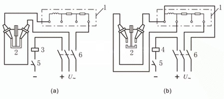
Figure 1: shows the wiring diagram of the circuit breaker opening and closing time measurement principle
(a) Opening time measurement; (b) Closing time measurement
1- Electric stopwatch; 2- Switch contacts; 3- Opening winding; 4- Closing winding; 5- Switch; Power switch
In Figure 1(a), first switch on switch 5. Then switch on power switch 6, the electric stopwatch 1 and the circuit of the opening winding 3 are turned on at the same time, and the electric stopwatch 1 starts timing; and the opening winding starts the circuit breaker to open, and The switch contact 2 is separated, and the electric stopwatch stops timing due to power failure. At this time, the time recorded by the electric stopwatch is the fixed time of the circuit breaker. As shown in figure (b), switch 5 is closed first, then switch 6, at this time, the closing winding 4 and the electric stopwatch 1 are connected at the same time, and the electric stopwatch starts timing. When the moving contact of the circuit breaker is turned on, the electric stopwatch Stop timing, and the time recorded by the stopwatch is the closing time of the circuit breaker.
Although the electric stopwatch is simple, the measurement error is caused by the start-up time of the electric stopwatch itself and the unsynchronization of the power switch, which makes the dispersion larger. It should be measured at least 3 times and the average value is taken. But when there is no more advanced measuring instrument, the measurement is relatively simple.
2. Measurement method of three-phase synchronization difference.
(1) The switch can be manually opened and closed slowly, and the difference in the stroke of each phase can be used to approximate the synchronization difference of the circuit breaker action. The wiring diagram is shown in 2.
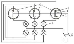
Figure 2: Wiring diagram for measuring the synchronization difference of the circuit breaker with the light method
1- Breaker moving contact; 2- Breaker static contact; 3- Bulb; 4- Breaker
The light bulb 3 is connected in series with the moving and static contacts of the circuit breaker 4. Turn on the power switch S to watch the light and dark sequence of the light bulb in the slow opening and slow closing process, that is, the sequence of the contact or separation of the moving and static contacts of each phase. Measure the stroke difference of each phase with a ruler to approximate the synchronization difference of the three-phase action.
(2) For fast circuit breakers, oscilloscope recording or digital millisecond meter should be used to measure the synchronization difference, and accurate results can be obtained. The measurement wiring diagram is shown in Figures 4 and 5. The currently used light oscilloscope does not need to process the film, and can be directly irradiated with fluorescent light or sunlight on the photosensitive line, which is very convenient.
The oscillogram can be used to calculate opening and closing and different periods. For example, time tab is the number of cycles of the time scale spanned by the ab segment multiplied by the period T of the time scale. Time scale frequency f=1000Hz, then period T=1/f=1 (ms), namely tab=nT(ms). Among them, n is the number of time scale cycles spanned by the ab segment.
The three-phase circuit breaker can also be measured as shown in Figure 3. In this way, the second wave recording can measure the opening and closing and synchronization difference.
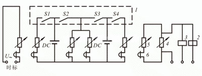
Figure 3: Principle wiring diagram of measuring circuit breaker action time with electromagnetic oscilloscope
1- circuit breaker; 2- opening winding; 3- closing winding; 4- shunt; 5- voltage divider;
6-oscilloscope vibrator; S1~S4- fracture; DC-battery
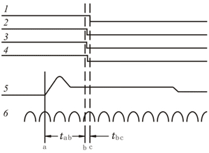
Figure 4: Recording diagram of circuit breaker opening
1~4-The waveform of the fracture; 5-opening current line; 6-time scale; tab-opening time; tbc-opening synchronization difference
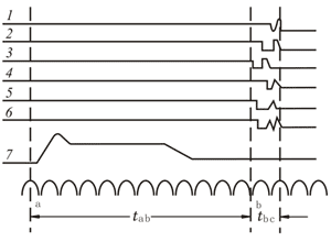
Figure 5: Recording diagram of circuit breaker closing
1~6-The waveform of the fracture; 7-closing current line; tab+tbc-closing time; tbc-closing synchronization difference.
3. Special circuit breaker dynamic characteristic tester to measure.
At present, due to the development of science and technology, various types of complete measuring instruments have been manufactured for the characteristic measurement of circuit breakers, which are not only convenient to use, but also accurate in measurement data; a switch dynamic characteristic tester can measure various parameters. Such as GKC-Y high-voltage switch dynamic characteristic tester, suitable for various circuit breakers to measure opening and closing time, synchronization; closing and opening instantaneous, average and maximum speed, as well as lift distance, over distance, etc.; it can also measure bounce time, The number of times and the maximum bounce amplitude, etc.

